本文共 6212 字,大约阅读时间需要 20 分钟。
一、SPI概述
SPI(Serial Peripheral interface)就是串行外围设备接口,是一种串行的主从接口,集成在很多微控制器内部。SPI是一种高速的,全双工,同步的通信总线,并且在芯片的管脚上只占用四根线,节约了芯片的管脚,同时为PCB的布局上节省空间,提供方便。SPI接口主要应用在 EEPROM,FLASH,RTC,实时时钟,ADC,还有数字信号处理器和数字信号解码器之间。
SPI的四根线分别为
SDI(MISO) :主器件数据输入,从器件数据输出
SDO(MOSI) :主器件数据输出,从器件数据输入
SCLK:时钟信号,由主器件产生。
CS:从器件使能信号,由主器件控制选择实能哪个器件
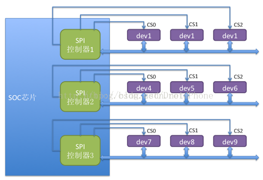
spi主从硬件连接图

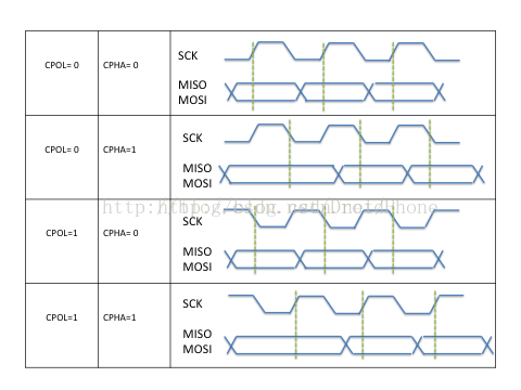
工作时序:
按照时钟信号和数据信号之间的相位关系,SPI有4种工作时序模式:
更详细参考这个:
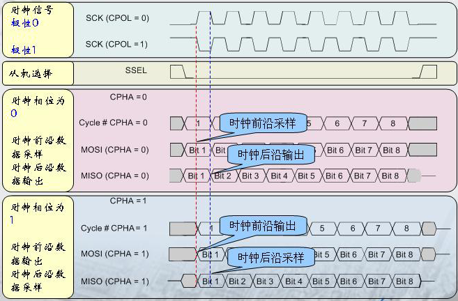
我们用CPOL表示时钟信号的初始电平的状态,CPOL为0表示时钟信号初始状态为低电平,为1表示时钟信号的初始电平是高电平。另外,我们用CPHA来表示在那个时钟沿采样数据,CPHA为0表示在首个时钟变化沿采样数据,而CPHA为1则表示要在第二个时钟变化沿来采样数据。内核用CPOL和CPHA的组合来表示当前SPI需要的工作模式:
CPOL=0,CPHA=1 模式0 CPOL=0,CPHA=1 模式1 CPOL=1,CPHA=0 模式2 CPOL=1,CPHA=1 模式3
二、linux SPI总线架构
在2.6的linux内核中,类似I2C的总线架构,SPI的驱动架构可以分为如下三个层次:SPI 核心层、SPI主机控制器驱动层和SPI设备驱动层。

Linux 中SPI驱动代码位于drivers/spi目录中
1、spi核心层
spi核心层是spi总线的核心部分,提供了核心数据结构的定义、spi控制器驱动和spi设备驱动的注册、注销方法的API。其为硬件平台无关层,向下屏蔽了物理总线控制器的差异,定义了统一的访问策略和接口;其向上提供了统一的接口,以便SPI设备驱动通过总线控制器进行数据收发。
SPI核心层的代码位于:driver/spi/ spi.c (这一个文件分析后续有待补充。。。)
IO模拟SPI接口代码位于:drivers/spi/spi_gpio.c
2、spi控制器驱动层:
SPI控制器驱动层,每种处理器平台都有自己的控制器驱动,属于平台移植相关层。它的职责是为系统中每条SPI总线实现相应的读写方法。在物理上,每个SPI控制器可以连接若干个SPI从设备。
在系统开机时,SPI控制器驱动被首先装载。一个控制器驱动用于支持一条特定的SPI总线的读写。一个主机控制器驱动可以用数据结构struct spi_master来描述,其主要成员是主机控制器的序号(系统中可能存在多个spi主机控制器)、片选数量、spi模式和时钟设置用到的函数、数据传输用到的函数等。
在include/liunx/spi/spi.h文件中,在数据结构struct spi_master定义如下:
struct spi_master { struct device dev; s16 bus_num; //该控制器对应的SPI总线号 u16 num_chipselect; //控制器支持的片选数量,即能支持多少个spi设备 //设置SPI总线的模式,时钟等的初始化函数, 针对设备设置SPI的工作时钟及数据传输模式等。在spi_add_device函数中调用 int (*setup)(struct spi_device *spi); int (*transfer)(struct spi_device *spi, struct spi_message *mesg); //实现SPI总线读写方法的函数。实现数据的双向传输,可能会睡眠 void (*cleanup)(struct spi_device *spi); //注销的时候调用}; 分配、注册和注销spi主机的API由SPI核心提供:
struct spi_master * spi_alloc_master(struct device *host, unsigned size);int spi_register_master(struct spi_master *master);void spi_unregister_master(struct spi_master *master);
3、spi外设驱动层
SPI设备驱动层为用户接口层,其为用户提供了通过SPI总线访问具体设备的接口
SPI设备驱动层可以用两个模块来描述,struct spi_driver和struct spi_device
相关的数据结构如下:
struct spi_driver { int (*probe)(struct spi_device *spi); int (*remove)(struct spi_device *spi); void (*shutdown)(struct spi_device *spi); int (*suspend)(struct spi_device *spi, pm_message_t mesg); int (*resume)(struct spi_device *spi); struct device_driver driver; }; Driver是为device服务的,spi_driver注册时会扫描SPI bus上的设备,进行驱动和设备的绑定,probe函数用于驱动和设备匹配时被调用。从上面的结构体注释中我们可以知道,SPI的通信是通过消息队列机制,而不是像I2C那样通过与从设备进行对话的方式。
struct spi_device { struct device dev; struct spi_master *master; u32 max_speed_hz; u8 chip_select; u8 mode; u8 bits_per_word; int irq; void *controller_state; void *controller_data; char modalias[32]; }; 在spi外设驱动中,当通过spi总线进行数据传输的时候,使用了一套与cpu无关的统一的接口。这套接口的第一个关键参数就是spi_transfer,它用于spi的传输。
struct spi_transfer { /* it's ok if tx_buf == rx_buf (right?) * for MicroWire, one buffer must be null * buffers must work with dma_*map_single() calls, unless * spi_message.is_dma_mapped reports a pre-existing mapping */ const void *tx_buf; void *rx_buf; unsigned len; dma_addr_t tx_dma; dma_addr_t rx_dma; struct sg_table tx_sg; struct sg_table rx_sg; unsigned cs_change:1; unsigned tx_nbits:3; unsigned rx_nbits:3;#define SPI_NBITS_SINGLE 0x01 /* 1bit transfer */#define SPI_NBITS_DUAL 0x02 /* 2bits transfer */#define SPI_NBITS_QUAD 0x04 /* 4bits transfer */ u8 bits_per_word; u16 delay_usecs; u32 speed_hz; struct list_head transfer_list;}; 而一次完整的spi传输流程可能不只是包含一次spi_transfer,它可能包含一个或多个,而这些spi_transfer最终通过spi_message组织在一起
struct spi_message { struct list_head transfers; struct spi_device *spi; unsigned is_dma_mapped:1; /* REVISIT: we might want a flag affecting the behavior of the * last transfer ... allowing things like "read 16 bit length L" * immediately followed by "read L bytes". Basically imposing * a specific message scheduling algorithm. * * Some controller drivers (message-at-a-time queue processing) * could provide that as their default scheduling algorithm. But * others (with multi-message pipelines) could need a flag to * tell them about such special cases. */ /* completion is reported through a callback */ void (*complete)(void *context); void *context; unsigned frame_length; unsigned actual_length; int status; /* for optional use by whatever driver currently owns the * spi_message ... between calls to spi_async and then later * complete(), that's the spi_master controller driver. */ struct list_head queue; void *state;}; 通过spi_message_init()口语初始化spi_message,而将spi_transfer添加到spi_message队列的方法则是:
void spi_message_add_tail(struct spi_transfer *t, struct spi_message *m)
发起一次spi_message的传输有同步和异步两种方式,使用同步api时,会阻塞等待这个消息被处理完:
int spi_sync(struct spi_device *spi, struct spi_message *message)
使用异步spi时,不会阻塞,但是可以在spi_message的complete字段挂接一个回调函数,当消息处理完,函数会被调用:
int spi_async(struct spi_device *spi, struct spi_message *message)
下面给出spi传输的例子:
static int tsc2005_write(struct tsc2005 *ts, u8 reg, u16 value){ u32 tx = ((reg | TSC2005_REG_PND0) << 16) | value; struct spi_transfer xfer = { .tx_buf = &tx, .len = 4, .bits_per_word = 24, }; struct spi_message msg; int error; spi_message_init(&msg); spi_message_add_tail(&xfer, &msg); error = spi_sync(ts->spi, &msg); if (error) { dev_err(&ts->spi->dev, "%s: failed, register: %x, value: %x, error: %d\n", __func__, reg, value, error); return error; } return 0;}static int tsc2005_read(struct tsc2005 *ts, u8 reg, u16 *value){ struct tsc2005_spi_rd spi_rd; struct spi_message msg; spi_message_init(&msg); spi_message_add_tail(&spi_rd.spi_xfer, &msg); return spi_sync(ts->spi, &msg);}
spi外设驱动遍布于内核的drivers、sound等各个子目录下,spi只是一种总线,spi_driver的作用只是将spi外设挂接在该总线上,因此在spi_driver的probe()成员函数中,将注册spi外设本身所属设备驱动的类型。
和platform_driver对应这一个platform_device一样,spi_driver也对应这一个spi_device,platform_device需要在bsp的板级文件中添加信息数据,而spi_device同样也需要,记录了spi外设所使用的主机控制器序号、片选序号、数据比特率、spi传输模式(spol、cpha)等
可以参考:arch/arm/mach-omap1/board_nokia.c
linux3.x后的内核改为设备树后,不再需要arch/arm/mach-xxx板级信息了,倾向于在spi控制器节点下填写子节点
可以参考:arch/arm/boot/dts/omap3-over-common-lcd43.dtsi中包含的ads7846节点